ATmega 128 Prototyping Board


This little project started off with a large graphical VFD. I wanted to make a controller board for that display so it could be controlled from a PC (or other device) via USB. But when I started to draw up the schematics, I ended up with a more generic design that made it possible to use the Atmel ATmega128 (and compatible) in different projects.

The idea behind this page it to provide some help for those who had got a board from me (or made one yourself from my plans). You can find schematics, placement drawings and port usage pictures here as downloadable pdf-file.

There are actually not much to describe about this. A rather simple and small board that allows you to play around with an ATmega128 (verified) or pin-compatible (ATmega1281 or ATmega2561, these are not yet verified). To summarize the design, the following features are avaiable:
Building the thing

This build requires SMD-mount skills. Best to start with this so You are prepared. The smallest parts are 1206-sized resistors and capacitators. The FT232RL is in a SSOP-28 and the ATmega is a TQFP-64.

First of all, You will need these parts to build this thing:

Value Position Type Note
330 ohm R1, R4, R5 1206 Value may be adjusted depending on LED selection.
4.7 kohm R2 1206 Optional - Used at external power only.
6.8 kohm R7 1206 Adapt value to application.
10 kohm R3 1206 Optional - Used at external power only.
10 kohm R6 1206  
XX pF C6, C7 1206 Must be matched with crystal if used.
100 nF C2 - C5, C8 - C12 1206  
22 uF/10 V C1 EIA 6032 Tantalium type.
XX MHz X1 HC49 Choose any within ATmega specification.
32.768 kHz X2   Clock crystal
3 mm LED D1, D2, D3 Choose any color you like...
ATmega128 U1 TQFP64 Could be replaced with ATmega1281/2561.
FT232RL U2 SSOP-28  
2-pin strap JP1, JP3, JP4   2.54 mm spacing
4-pin strap JP2   2.54 mm spacing
Pushbutton B1 6 x 6 mm ALPS
6-pin header J10    
10-pin header J4, J5, J6, J8, J9    
26-pin header J2, J3    
USB-B J1   USB type B PCB connector

The easiest way to build this board is to start with the two IC's, followed by the other SMD parts. Then, mount LED's, reset button and crystal(s). Finish the build by mounting the strapping headers and all pinheaders. This board should be an easy task if you have done SMD before. If not, then search the net - there are some decent guides around (or get someone to help you).

This board allows some different setups regarding power supply and MCU clock. The selection involves selecting some parts to be mounted and some to leave out. Below are the combinations that could be used for power: To avoid mistakes, there are some simple rules to follow:

1. Don't apply multiple power sources. Choose one and stay with it. If changed (specially if Vtarget have been used), be sure that the board is properly reconfigured.

2. R2 and R3 should not be used if power is taken from USB.

3. There is no polarity protection at the board. Beware of that when connecting to J7. USB or Vtarget does not have the risk as reveres polarity can't be done.

4. 3.3 V power could be used, but only via J7.

Next up are the clock options: Regarding the rest of the board, just use the pinheaders you want. If you don't use all ports, just skip these if cost is an issue. The GU300-connector (J2) contains the complete port B and partly port D (0 - 4). The complete port D is avaiable at J4. Just note that PD0 - PD4 are duplicated in J2 and J4.

This board is mainly build around the ATmega128 MCU, but it could be used with ATmega1281 and ATmega2561 too as these models are pin-compatible with the 128.

If you don't need the USB-port, then it is ok to skip these parts entirely. They are J1, U2, C3 - C5, D2, D3, R2 - R5 and JP2. A regular serial port could be connected to port E (J5). RXD0 is at pin 1 and TXD0 is at pin 2. Any level conversion has to be done outside the board, using a MAX232 for example. Even if you have the USB fitted, you could use RXD0/TXD0 as a regular com-port by removing the JP4 (power is still avaiable from USB).

A nice feature by having the FT232R at the board is the possiblility to have the clock from it. The board is designed to allow the CBUS4 signal to be connected to XTAL1 of the ATmega. By doing this, you could save a crystal and two caps. You have to program the ATmega to use an external oscillator for this feature. You have totally four different frequencies to choose from: 6 MHz, 12 MHz, 24 MHz and 48 MHz. For a ATmega128, the two lower frequencies could be used as the chip is rated for max 16 MHz. The actual selection of frequency at CBUS4 is done via a tool provided by FTDI (you can find it at their homepage) called MProg. Current version (when this was written) is 3.0a.

Before you can use the tool (or the USB-serial function at all) you must install a Windows driver. This one is also avaiable at the FTDI homepage. You should use the VCP-drivers and they are compatible with all Windows-versions from 2000 and up, including Vista. Running 64 bit? Not a problem - they work for 64 bits versions of XP, Vista and Server 2003 too. The installation of the drivers follows standard Windows procedure. First download the VCP package and store it in a temporary place at the harddisk. Unpack it with WinZIP or similar tool. Now, plug in your ATmega-board into a free USB-port. The "Found new hardware"-guide will pop-up. Deny all request for automatic search of internet and CD/DVD. Instead, point the guide to the directory where you have unpacked the driver files. Finish the installation and reboot the PC if requested.


Add-on board with ethernet and SRAM-expansion

This is a useful upgrade to the ATmega128 prototype board. It adds on three useful features that did not make into the base design: Currently, this part is still in development. The schematics design and board layout work is done an the first series of boards have been manufactured and built (see pictures far below). Next step is to write some software that tests through all the functions of the board.


Downloadable files
Useful links
The Pictures (of course)


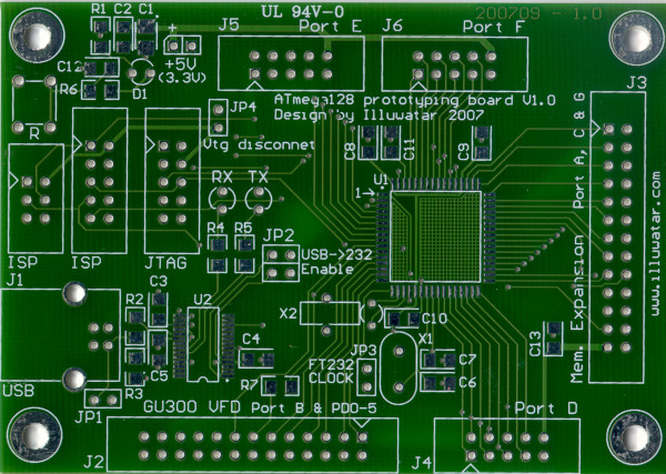
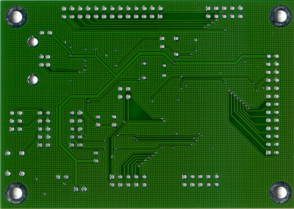
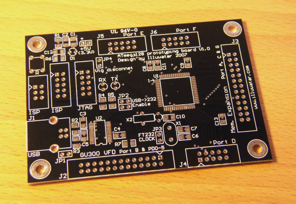
Bare board, made by PCBCart.


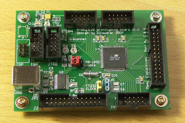
The assembled board, configured for USB-power and 12MHz clock from FT232R.


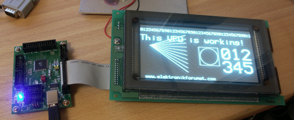
The board hooked up to a massive Noritake Itron GU256x128-300.


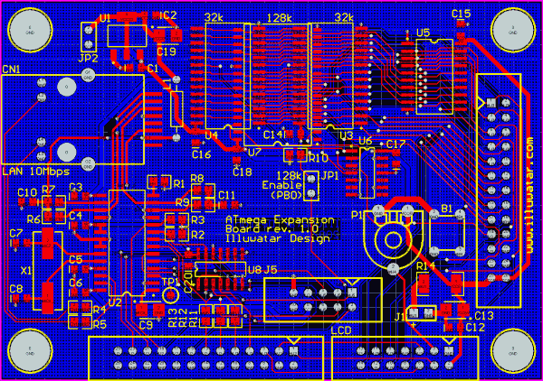
The upcoming add-on board with ethernet (10 Mbps) and SRAM.


The Black Edition ;-) (same thing, different color...)


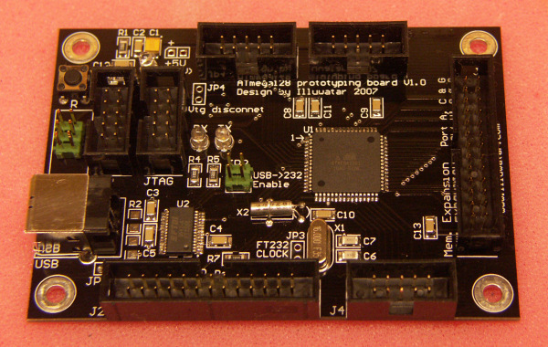
The Black Board, all populated


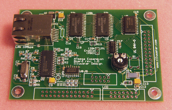
The first version of the add-on board with ethernet and RAM (64k x 8 at the picture)


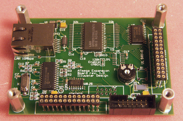
This board have been fitted with a single 128k x 8 SRAM chip

Latest update: 2007-12-19