Mini-ITX MiniMig Version 2.0
Disclaimer:
- This project is based on Dennis van Weeren Minimig. The original design and the firmware for PIC and FPGA is his work. The Minimig is released under the GPL License
and so are also my modifications.
The orignal Minimig is found at this web page: http://home.hetnet.nl/~weeren001/. At this page, you can find all the sources for the Minimig
(I will only provide complied binaries that have been verified with my board).
- To use the Minimig (both my and Dennis version) requires a Amiga Kickstart ROM-file. This file is still a copyrighted piece of software, so I can't provide You with it. You need a actual Amiga
to download it from (tools for it are avaiable in the WinUAE project) and put it on the MMC/SD-card.
To the Project
The first incarnation of the Mini-ITX MiniMig did have some issues, preventing it from being a reproducable unit that could be sold to other people. There was some actual faults in the design and there was some
less successfully implementations. To summarize the whole thing:
- Video amplifier corrected - it needs negative voltage to operate properly. This fix made the VGA output to work... ;-)
- Changed back to DIP-based PIC - by doing this it is possible to remove it and reprogram it in case of trouble.
- Improved ground planes - less EMI emission from the device and better analog signals (video).
- ESD-protections at the ports.
- Simplified power regulation - only the main +5 V is switched now, the rest are linear (800 mA LDO). This reduces both noise and cost.
- Dual-PIC configuration: it is possible to select between PIC18LF252 or PIC18LF452. With the larger model, more ports are available for own experiments.
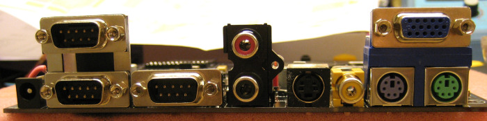
- All connectors are now at the rear of the PCB. This is neccessary to be 100% Mini-ITX.
All these features/corrections was needed to make the board suitable for others to build. The board is still 100% compatible with the Dennis PIC firmware and FPGA core. That includes the modified
and improved ones. The analog video outputs may have limitations depending on core modifications, but the VGA output will always work. For those out there who like tinkering with stuff (who aren't?),
there are some options available: dual socket for original PIC or a larger PIC for more I/O, full access to the video outputs of the FPGA (for own video interface circuits - LVDS/DVI anyone?) and the
spare pins in a special connector with mounting holes for a daughterboard design, all ports available via pin headers (good for case designers) and finally, the LEDs and buttons could be connected via
a header too.
The board is finished in design, but there are some things to do before a complete release is possible: Finalize the PCB (some cosmetic issues left), generate pdf's from the schematics and PCB layout
and when all is 100% correct, put up the original Protel files too.
I have made an adapter for the SD-card reader that connects to the header on the MiniMig. This allows the user to relocate the card reader to a more suitable place in the case. These will be ordered
at the same time as the updated MiniMig boards. The Protel-files for the adapter has been added to the links below.
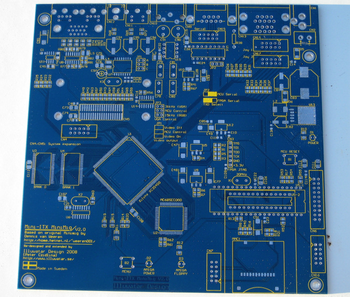
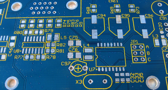
Update 2008-12-19: The design has been tested successfully with 10 ns SRAM from Cypress. This is now an option to the standard 55 ns. I also got the final test run of the PCB design. This time, I made
the board blue with yellow markings. They came out very nice - I think I prefer this color combination ahead of the black.
Update 2009-01-22: Bought the PIC replacement board from Jakub (Yaqube). This tiny device gives the MiniMig some ARM power that allows more tricks to be done. One of them is the hard file feature, making
it possible to run the MiniMig from a virtual hard disk. Also, there is a improved configuration that is totally controllable with the joystick. And finally, you can overclock the MiniMig, both the CPU and
the floppy interface. My board was designed from the beginning to house this tiny gem and as the pictures below indicates, it fits just perfectly. And it runs perferctly too...
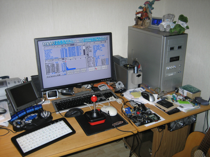
Update 2009-02-12: Development of the firmware for the ARM controller is in progress. I'm the beta-tester for Yaqube. Also, I finally managed to get 60 Hz VGA out of the board (thanks to the Yaqube software).
There is no problem running the board on my 40" Samsung LCD...
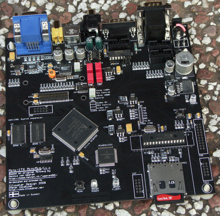
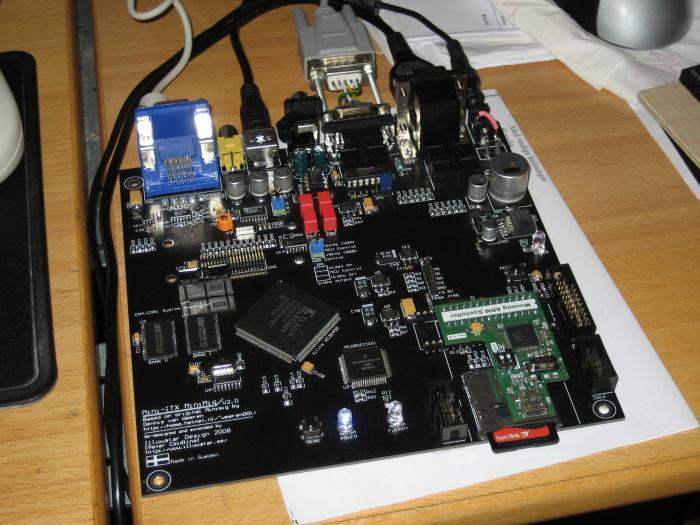
Update 2009-03-29: The first complete blue V2.0 board completed, tested and working (and I have a customer for it too). More boards will be built when the finances allows it. This should be the final incarnation
of the 2.0-line.
Enjoy the pictures below...
Project Files:
Web-links related to this project:
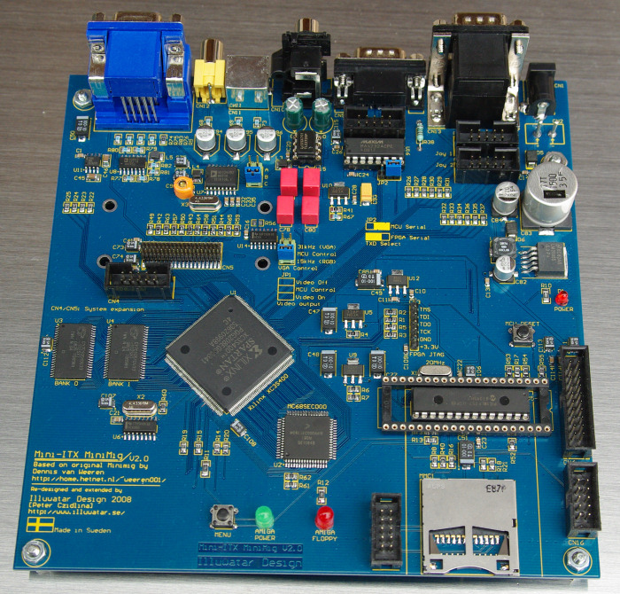
The blue version - finally done and working...
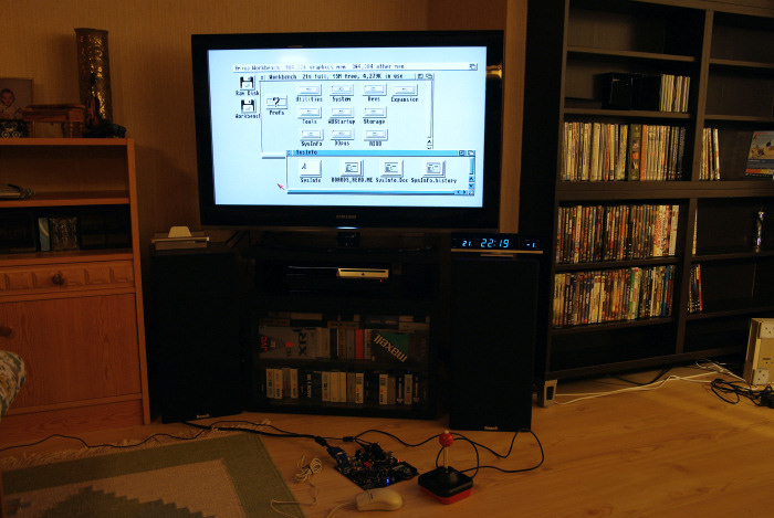
40" Workbench... (the light trow the colors little bit off)
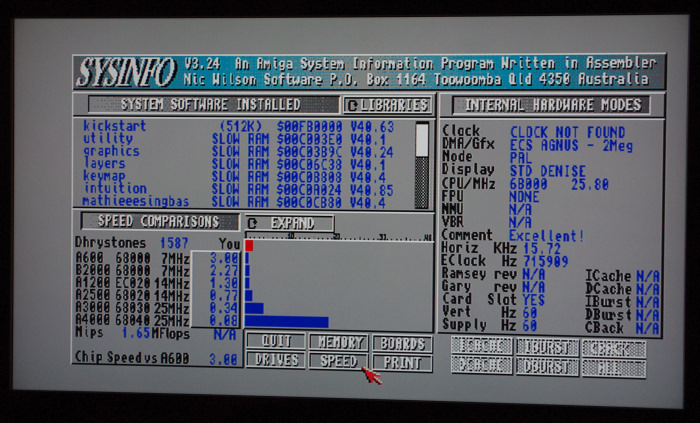
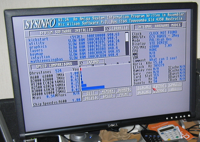
CPU overclocking in ARM firmware. Close shot of the 40" LCD with no disturbing lights around.
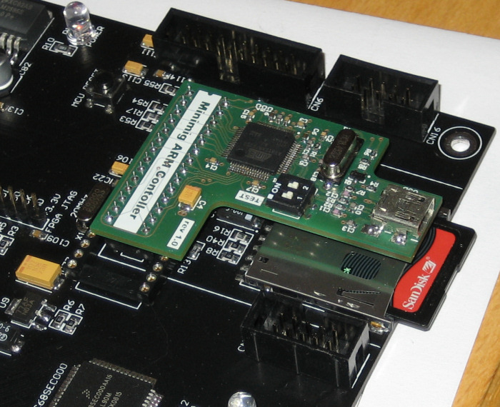
The ARM controller board from Yaqube (Jakub) that replaces the original PIC.
Fits just nice on my design...
The proof that it runs - the board has booted a hard-file with WB 3.1.